12 Describe Forming Limit Diagram and Its Usefulness
Describe different forming processes when they might be used and compare their production rates costs and environmental impactscalculate forming forces predict part defects tearing wrinkling dimensional inaccuracy and propose solutionsexplain current developments. FORMING LIMIT DIAGRAM meaning - FORMING LIMIT DI.

Forming Limit Diagram An Overview Sciencedirect Topics
The higher is its curve in the forming-limit diagram.

. Generally speaking integral criteria eg. Forming limit diagram is extensively used in the analysis of sheet metal forming to define the limit of deformation of materials without necking or fracture. What does FORMING LIMIT DIAGRAM mean.
12 department of mechanicalengineering PO Box 513 5600MB Eindhoventhe Netherlands Forminglimit diagramsfor sheet deformation processes EMViatkinaWAM. Its main advantage sheet metals. It is necessary to.
The forming limit diagram FLD also known as the KeelerGoodwin diagram was originally derived as an experimental semiquantitative tool to aid designers in evaluating the risks of local fracture and necking in sheet forming Wagoner et al 2001. Contents Description Modern determination Influence parameters M-K method Use of FLCs. There are many methods to obtain the forming limit diagram.
In a variety of methods of evaluating the formability of materials the forming limit diagram FLD is the most intuitive and effective and the most widely used. The onset of local necking is given by the forming limit strain FLS. Opportunities and challenges Objectives.
Forming Limit Diagram FLD is used during the design stage of any new sheet metal component for tooling shape optimizing variables. ABSTRACT A number of ductile failure criteria are nowadays being used to predict the formability of aluminium alloy sheets. I material A minor axis of -20 and major axis of 40 ii material B minor axis of 10 and major axis of 70 Indicate the position of materials A and B on the diagram and describe which material has better formability.
1 2 The diagram attempts to provide a graphical description of material failure tests such as a punched dome test. Forming limit diagram plays an important role on the analysis of plastic deformation of sheet metals. Review Sekhara Reddy A C1 TPavan Kumar2 1Professor Sreyas Institute of Engineering and Technology Hyderabad India.
It is now used frequently in failure diagnosis of sheet forming processes and has been implemented in most sheet forming. The FLC provides the forming limit strain FLS which is the strain that a sheet can withstandbeforelocalneckingAdeformationconditionbelowthe. Reducing the overall price of the products.
So any strain state in the red area indicates a failure due to necking. The forming limit curve FLC is the plot of critical major strain vs. Forming limit is one of the important indexes to evaluate the formability of materials.
1A forming-limit diagram provides severity bands the height of the bands on the major strain axis and the location of the measured strain point. In the left side of the Forming Limit Diagram FLD. Describe how to construct a Forming Limit Diagram FLD c.
Numerical method to predict forming limits in weld materials and verifying deformation and forming limit predictions. 12 Citations 291 Downloads Abstract First introduced in 1963 forming limit diagrams FLDs have been empirically constructed to describe the strain states or combinations of major e 1 and minor e 2 principal strains at which a highly localized zone of thinning or necking becomes visible in the surface of sheet metal. Explain why the inhomogeneity factor ϕ in rod and wire drawing depends on the ratio hL as plotted in Fig.
2HOD Department of Mechanical Engineering NNRG Hyderabad India Abstract The accurate description of forming. The paper introduces a experiment method for determination of forming limit curve for whole range of the FLD for sheet metal. The Forming Limit Diagram is more commonly used in simulation analysis whereas Circle Grid Plots are more useful on the shop floor.
A forming limit diagram also known as a forming limit curve is used in sheet metal forming for predicting forming behavior of sheet metal. For a clearer understanding we can change the background colors in the diagram. This year the forming-limit diagram FLD celebrates 50 years of helping improve sheetmetal forming.
INTRODUCTION In the industrial practice it is often important how the forming process is performed. This curve represents the limit of forming without cracks. For the FLD diagrams shown below Figure 3.
In sheet metal industry and. Forming limit diagrams FLD experiment method 1. What is a Forming Limit Diagram FLD.
The area above the FLC has been changed to red. As an important tool in properties study and defect prediction of sheet metal forming forming limit diagram has been used. Geers Netherlands Institutefor Metals Research Eindhoven University of TechnologyDepartmentof Mechanical Engineering Introduction.
The FLD was developed from a 4-yr. Many toolmakers may also prefer to study a circle grid plot rather than an FLD diagram but ideally both a circle grid plot and an FLD should be studied together to get the best understanding of how the material is behaving during the forming. The approach relied on developing standardized test methods for weld material populations to establish a statistical description of material imperfection and mechanical properties in their weld region and developing statistically based forming limit diagrams FLD.
The forming limit diagrams are also consists in shortening the time needed for the design used by commercial finite-element codes as a of the technological processes and consequently in limiting criterion of the forming process. FLC plots the major strain at the onset of localized necking for all values of the minor strain at different loading paths. Those proposed by Cockcroft and Latham Brozzo et al Oyane et al Chaouadi et al etc have been probed to work well when the principal strains are of opposite sign ie.
A forming limit curve FLC is a curve of deformation limit generally governed by localized neckingthat associates with ductile fracture. Describe a the similarities and b the differences between the bulk deformation processes described in Chapter 6 and the sheet-metal forming. It is called the Forming Limit Curve FLC.
Graduate research program that sought to determine.

Sheet Metal Forming An Overview Sciencedirect Topics

Formability An Overview Sciencedirect Topics

Incremental Forming An Overview Sciencedirect Topics
2

Forming Limit Diagram An Overview Sciencedirect Topics

Materials And Design
2

Formability An Overview Sciencedirect Topics
2
2
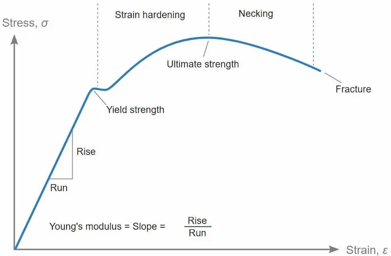
Stress Strain Curve How To Read The Graph

Sheet Metal Forming An Overview Sciencedirect Topics
2

Localized Necking An Overview Sciencedirect Topics

Forming Limit Diagram An Overview Sciencedirect Topics

Forming Limit Diagram An Overview Sciencedirect Topics
Forming Limit Diagram An Overview Sciencedirect Topics

Strain Rate Sensitivity An Overview Sciencedirect Topics

Forming Limit Diagram An Overview Sciencedirect Topics


Comments
Post a Comment